Alfa Romeo Forums banner
21 - 40 of 48 Posts
My 2017 Giulia starter failed to energize the other day. No DIC (driver information message). no DTC's (diagnostic trouble codes), no nothing to explain why the engine would not turn over.

Knowing that there has been a history of starter relay failures, I looked for and found the culprit relay. Once I found the bad relay, I grabbed the heated rear window relay from the rear PDC (power distribution center) and swapped it. On the road again! This is the second relay to go bad while owning the car since new. Guess I will have to get a few few spare relays to carry in the console along with spare fuses. Beats paying $100's to get flatbedded to the "nearest" dealer!

View attachment 1636105
View attachment 1636106
View attachment 1636107
Howdy. My relays are accessible by reaching through a narrow spot to passenger side of radiator (LHD car). I had to first squeeze tabs on a cover box to remove and expose the relays. There are two boxes there.see photos.
Image
Image
w
 
I am having a problem as well.. I have ordered 5 of the parts to just replace all 5 of them for ease of mind. How did you guys manage to wiggle them out of the clip/holders? I have been able to expose them by taking the plastic covers out. Thanks!
 
Prise away the center from the surrounding fixture, then remove the entire clip. The job will be much easier with the road wheel removed.
 
NAPA's Echlin AR6034 mini relay works ($21.99) although only listed for Lexus. Nobody seems to list Alfa Romeo. (WARNING: This relay is known to the State of California to cause Cancer and Reproductive Harm. Please do not eat!)
View attachment 1646398
I replaced the far inboard relay after removing the fender liner described earlier. Car started the next morning but left me stranded after work when my temp gage read 118. I looked back on this site and saw there was a second relay shown on the wiring diagram. Not real sure where it was physically located, but I made an assumption it was next to the one I just replaced. After now realizing exactly where it was located, I opened the hood and looked in the vicinity I thought I was reaching for inside the inner fender well. It is right there. Reach it and pull cover off. Pull out relay. Smack it on the ground 3X. Put it back in. Start car. Drive to Napa and bought the above described relay at an increased price. It takes less than 90 seconds start to finish to replace from under the hood. Blue one pictured is first one I replaced. I then replaced the outboard OEM red relay with this new Napa relay.
Image
Image
Image
Image
 
My 2017 Giulia starter failed to energize the other day. No DIC (driver information message). no DTC's (diagnostic trouble codes), no nothing to explain why the engine would not turn over.

Knowing that there has been a history of starter relay failures, I looked for and found the culprit relay. Once I found the bad relay, I grabbed the heated rear window relay from the rear PDC (power distribution center) and swapped it. On the road again! This is the second relay to go bad while owning the car since new. Guess I will have to get a few few spare relays to carry in the console along with spare fuses. Beats paying $100's to get flatbedded to the "nearest" dealer!

View attachment 1636105
View attachment 1636106
View attachment 1636107
How did you remove the relay holders from where they are hanging?
 
Discussion starter · #27 ·
How did you remove the relay holders from where they are hanging?
Push the three relay/fuse assemblies up to release the clip tab from the metal mounting bar that holds them in place. Then drop the harness down to remove the covers. The hardest part for me was to slide the assemblies back on the bar! I finally removed the Torx screws mounting the wheel well liner and pulled it aside to make enough room for my hand. Still had to work it 'blind'. I have never been able to insert my arm and hand from the top as some others have suggested without ripping flesh. Perhaps AR relocated the mounting after my 2017.

Also, below is a schematic that shows that there are actually three relays controlling the starter circuitry. Two (one of which is referred to as T39) are operated by the Body Control Module (BCM, located behind the passenger side foot panel) and the thirdr (referred to as R6) by the ECM (aka. Power Control Module or PCM, located at passenger side of engine). I have not been able to figure out what the other three relays pictured below do. MOPAR's electronic Tech Authority does a really crappy job of mapping out the electrical systems.

All of this extra circuity appears to be required to allow the Engine Stop Start (ESS) and remote start systems to work. Very confusing even after studying it and very convoluted diagnostics. I think that this must be why it is just faster-easier-cheaper to replace all of the relays once access is gained and hope for the best.

Image

Image
 
Discussion starter · #28 ·
Engine Stop-Start System Explained (kinda)
(from MOPAR's Tech Authority Unit 08 Electrical / 8F -- Engine Systems / Starting)

Control Modules Involved in the Operation of the ESS System The ESS System Module Diagram shows the block chart of the components involved in first starting and operation of the ESS system. The initial starting is managed directly by the driver by pressing the Keyless Entry GO Start/Stop button.

When the start request and authentications are complete and processed by the Radio Frequency Hub Module (RFHM), Body Control Module (BCM), Powertrain Control Module (PCM aka. ECM) (Primary and Secondary) and the Electronic Steering Lock (ESL) module, relay T39 in the BCM and starter relay R6 managed by PCM will be managed to allow current to reach the starter motor and perform the first start operation.

Once the engine has started, the BCM holds its relay T39 closed while the starter relay R6 managed by the PCM will be open. The PCM will manage closing of the starter relay whenever the engine is started by the ESS system.

NOTE:If the starter motor remains powered after restarting the engine, the BCM will open its
own relay T39 to cut off current. The ESS system will be disabled.

Fault Operation The ESS system is disabled in case of a malfunction. The driver is informed by a warning indicator illuminating for general failure and, where provided, by the information message and by the icon of system failure on the IPC.
Image
 
Discussion starter · #29 ·
NO CRANK (BCM EQUIPPED)
(from MOPAR Tech Authority Unit 29 Non-DTC Diagnostics / Starting / Diagnosis and Testing)

Image

Theory of Operation
This vehicle uses a START/STOP Button for Keyless starting and for cycling the ignition on/off.

When the operator presses the Start/Stop Button, the FOBIK is validated wirelessly by the RF Hub (Radio Frequency Hub Module). If the FOBIK is recognized as belonging to the vehicle and is inside the vehicle, the system allows the ignition state of the vehicle to be changed by the operator between the LOCK, ACCESSORY, RUN, and START ignition states.

The RF HUB will log a DTC indicating an incorrect Ignition status value is present; in this state the ignition status is unknown. This will continue until the correct signal is received by the RF Hub.

EVIC Operation

The Keyless Go feature requires the vehicle to be equipped with an EVIC display for prompts and status information. The display messages are:


  • Service Keyless System
  • FOB Not Detected
  • FOB Left Vehicle
  • Not in Park
  • Push Brake Pedal and Push Button to Start
  • Push Clutch Pedal and Push Button to Start
  • Vehicle not in Park Warning
BCM/RF Hub Module Interaction

There are a few things that must take place before the starter relay can apply voltage to the starter. Below are some key points to check when diagnosing a no crank condition.

The BCM requires two signals from the RF HUB to verify the ignition is in the run or start position. The voltage on the F20 circuit is one of these signals. It can be monitored in both the RF HUB and BCM data display screens as the Ignition Run/Start under the “Sensor” value. The run or start position voltage on this circuit should be at or close to battery voltage.

Simultaneously the RF HUB busses the Ignition Run/Start status to the BCM. The BCM monitors the bussed input information as the secondary verification on the Ignition Run/Start status. The bussed messages can be monitored with the scan tool in both the RF HUB and BCM data display screens.

The F20 circuit voltage and the bussed ignition run/start status message received by the BCM must agree to enable starting. Once the vehicle is started, the loss of only one ignition signal will not cause the vehicle to cycle off as long as the other feed still indicates a "run status".

The RF HUB also requires an input from the Gated park switch (hardwired) and the OK to start CAN Bus message from the TCM (Crank Enable).

Diagnostic Aids


NOTE:
The No Crank Diagnostic serves as an aid in diagnosing the concern and is intended to be used as a general guide, since each no crank condition can be unique.

The No Crank Diagnostic Test assumes all of the following to be true:


  • Communication to all configured modules in the vehicle is possible with the scan tool.
  • The condition is currently present.
  • The TCM, PCM, RF HUB, and BCM are at the latest calibration (part number) levels.
  • There are no active DTCs.
  • There are no applicable Recalls.
  • There are no applicable TSBs.
  • There are no PCM inhibits (i.e. RPM, Trans Range, Clutch).
  • The FOBIKs complete function and operation is correct.
  • All battery cables and connections are clean and tight.
  • There are no open fuses.
  • The battery is fully charged and can pass a load test from the GR8 tester.
  • The engine rotates freely.
  • Any aftermarket equipment/wiring that has been installed is operating correctly.
Starter Relay Operation

In a no crank condition the Starter Relay can be missing power at pin 85, feed at pin 30, controlled ground at pin 86 or output at pin 87. Further explanation of how a relay operates is listed below:


  • Pin 85 receives power from the BCM once the parameters for the Ignition Switch position and status, and all inhibit monitors (i.e. clutch switch, RPM, etc.) are satisfied.
  • Pin 30 is a constant B+ feed.
  • Pin 86 is a controlled ground by a module (i.e. PCM or BCM). Once power is sent from the BCM to the pin 85 of the relay it passes through a coil and leaves the relay through pin 86 to the control module.
  • Pin 87 is an output circuit to the Starter solenoid. Once the circuit on pin 86 is grounded by the control module, the coil winding in the relay magnetically pulls the internal switch closed. When the internal switch is closed the power at pin 30 is sent to pin 87 of the relay.
Diagnostic Test

1. STARTER RELAY CHECK

1.​
When attempting to start the vehicle, listen and if needed feel for a click at the starter relay in the PDC.​


NOTE:
Some starter relays are internal to a module and may not be accessible, making it more difficult to hear, or feel the clicking response. It is possible for a poor ground or the Trans Range Sensor position to be lost causing the starter to click once.


Did you hear an audible click at the relay or starter?

Yes


  • Go To 9

No

  • Go To 2


2. STARTER RELAY INPUT CHECK

1.​
Use a 12 volt test light/DVOM to check for power at pin 85 of the starter relay.​


Is there Power/12 volts at pin 85?

Yes


  • Go To 8

No

  • Go To 3


3. RF HUB OPERATION

1.​
Using the scan tool, confirm the ignition switch status changes in the RF HUB under the data display screen for the “Sensor” values.​


Does the ignition switch status on the data screen change when pressing the START/STOP button?

Yes


  • Go To 5

No

  • Go To 4


4. REMOTE START ANTENNA


NOTE:
If the vehicle is not equipped with Remote Start, proceed to the next test step.

1.​
Cycle the ignition off.​
2.​
Disconnect the Remote Start Antenna from the RF HUB.​
3.​
Using one FOBIK and sitting in the driver’s seat, attempt to start the vehicle.​


Did the vehicle start?

Yes


  • Replace the Remote Start Antenna in accordance with the Service Information.
  • Perform the BODY VERIFICATION TEST.

No

  • Go To 5


5. BCM IGNITION STATUS

1.​
Using the scan tool, confirm the ignition switch status changes in the BCM under the data display screen for the “Bussed Input” and “Sensor” values.​


NOTE:
The change of status in the BCM for the “Sensor” value validates the voltage activity (with very low amperage) of the F20 circuit.


In the BCM, do both values for the ignition switch status match; and do they match those in the RF HUB?

Yes


  • Go To 6

No

  • If the status of the Ignition Switch position is not changing under the “Sensor” value, check the F20 circuit at the BCM for battery voltage with a DVOM (not a test light).
  • If there is Battery voltageat the BCM on the F20 circuit verify all power, ground and bus circuits are ok for the BCM. If no problem found replace the BCM in accordance with Service Information. (Refer to 08 - Electrical/8E - Electronic Control Modules/MODULE, Body Control/Removal and Installation) .
  • If there is NO Battery voltageat the BCM on the F20 circuit, then check for voltage on the F20 circuit at the RF HUB.
  • If there is Battery voltagecoming out of the RF HUB on the F20 circuit, check the F20 circuit between the RF HUB and BCM for a short, open condition or high resistance.
  • If there is NO Battery voltagecoming out of the RF HUB on the F20 circuit verify all power, ground & communication circuits, & connections to the RF HUB prior to replacing. (Refer to 08 - Electrical/8E - Electronic Control Modules/MODULE, Radio Frequency (RF Hub) /Removal and Installation) .
  • In the data screen, if the status of the Ignition Switch was not changing under the “Bussed Input” value, further diagnosis is needed between the RF HUB, (bus circuits, connections) and the BCM.


6. PCM IGNITION, TRANS RANGE/CLUTCH SWITCH STATUS VERIFICATION

1.​
Using the scan tool confirm there are no inhibits that have been triggered in the PCM (i.e. Ignition Switch, Trans Range or Clutch Switch) and any switch inputs (filtered states) relating to the starting system function and operate correctly under the data display screen.​


Does the PCM show any inhibits (not DTCs) for starting (not remote starting)?

Yes


No

  • Go To 7


7. BCM TO STARTER RELAY POWER INPUT CHECK

1.​
At this time if all the correct inputs for the ignition switch status are correct in the RF HUB, BCM and PCM, verify both power feeds are present (pin 30 and 85) to the Starter Relay while in the crank position.​


Are both power feeds present at the relay when the ignition is in the crank position?

Yes


  • Go To 8

No


8. STARTER RELAY CONTROL CIRCUIT CHECK

1.​
Using a test light/DVOM determine if the Starter Control circuit at pin 86 of the relay is missing ground (at the relay if equipped with a removable relay or wiring to the internal relay) when the ignition is in the crank position.​


Was the Starter Control circuit for pin 86 being grounded when the ignition was in the crank position?

Yes


  • Go To 10

No

  • Verify the Starter Relay Control circuit from pin 86, has no shorts, opens or high resistance on the wiring going from the Starter Relay in the BCM (or PDC) to the PCM.
  • Verify the cables do not have excessive resistance by performing a voltage drop on the battery cables.


9. STARTER RELAY OUTPUT CIRCUIT CHECK


NOTE:
At this point in the test, when the key is in the crank position power has been verified at Pin 30 & 85, along with the control circuit being grounded for pin 86.

1.​
Remove the Starter Relay Output circuit connector from the Starter solenoid.​
2.​
Using a test light/DVOM and ignition in the crank position check for power at pin 87 (If equipped with a removable relay or wiring to the internal relay) of the relay and at the connection to the starter.​


Was there power at pin 87 for the output circuit?

Yes


  • Go To 10

No

  • If power is missing to pin 30 of the starter relay the BCM is suspect. Verify all power, ground, communication circuits and connections to the BCM before replacing in accordance with service information.
  • If power is missing at pin 87 of the starter relay and the relay is replaceable, change out the relay and recheck the concern. If a known good relay causes no change, check the Starter Output circuit from pin 87 of the relay to the starter for an open, short, excessive resistance, or poor connections to the solenoid or starter.
  • Verify and Inspect the Starter to ensure it is free of corrosion, oil, and there is no damage, or binding conditions.
  • Verify that all wiring, cables and connections are clean and tight.


10. STARTER RELAY OUTPUT CIRCUIT LOAD TEST

1.​
Load test the Starter Relay output circuit going from the BCM to the Starter.​


Does the starter relay output circuit pass the load test?

Yes


No

  • Adjust the shift cable in accordance with the Service Information. Perform the POWERTRAIN VERIFICATION TEST.
 

Attachments

Don't give me too much credit. It is just that I invested in the 2017 AR Giulia Service Information CD from MOPAR's Tech Authority ($157.58 ). Since most of the Giulia drivers have not done so, I do not mind sharing what info I have been able to dig out of it.

I cannot speak to the hood latches since I have not delved that far into the sensors and gizmos. However, if you are not getting a light for an open hood, it does not sound likely. But most AR drivers would consider themselves lucky that the ESS is not working.

However, for about a year I would intermittently get DIC "Start-Stop Function Not Available". There were occasions when I had the message displayed and yet the engine would shut off at the traffic light but then fail to restart. I would press the Start Engine button to shut off power; reinitiate the engine start sequence, and then the engine would restart OK. An unnerving event to say the least when at a traffic light with cars in front pulling away and cars behind creeping up waiting for you to go! The dealer replaced the CAC (?) relay due to burnt contacts. That is when I learned of the short-lived relays. I eventually installed one of those devices from Centerline that defaults to ESS "off".
Seeing as you have the service info disc was wondering if you would be willing to help me out with my giulia? I left it sitting during covid and have been trying for months on end to get it to start. It's been in a state of "turns on and cranks but will not finish the startup". To list what I've done so far: I've replaced the relays mentioned in this post, changed the oil, drained the old gas/replaced with new gas, new spark plugs, primed the multi air system with oil, and changed battery. When I drained the old gas I did it by bridging open the fuel pump relay and hooking up a hose to the line under the hood. So I know that fuel is at least making it to just before the rail. I dont know how to test the injectors with what I have and was planning on trying to get to the throttle body to try starter fluid next if nothing else. At any rate, I'm at my wits end and can't afford taking it in for service at the moment so any guidance/info you could provide would be insanely appreciated.
There are a number of factors taken into account for modern, computer controlled cars to consider before an engine can be started. So the "no start" or "no fire" condition can be difficult to track down. An ESS (Engine Stop/Start) circuit adds to that algorithmic complexity. Alfa Romeo's diagnostics procedure start with a check of relays and fuses which, fortunately, are also the easiest to access and most likely culprits. Anything beyond that may require mechanical repair.

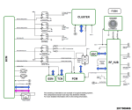
Theory of Engine Stop/Start (ESS) Operation: The ESS system uses two separate Starter Relays to control engine cranking. One relay is controlled by the Body Control Module (BCM). The other relay is controlled by the Powertrain Control Module (PCM). During a key start event, the BCM controlled Starter Relay 2 is commanded closed by the BCM. The Fused B+ output from the relay supplies voltage to the Fused B+ terminal (pin 30) of the PCM controlled Starter Relay. The PCM simultaneously commands Starter Relay 1 closed which allows the Fused B+ voltage to pass on to the Starter Solenoid. After the relay diagnostics have passed, the BCM controlled Starter Relay 2 is commanded on (closed), and the PCM controlled Starter Relay 1 is commanded off (open). During a Stop/Start event, the PCM controls cranking by opening and closing Starter Relay 1.

ESS Diagnostics: The PCM performs diagnostics on the Starter Relay control circuitry and the Starter Relay Output circuitry, as well diagnostics for a stuck closed Starter Relay. The PCM performs circuit fault detection diagnostics on the Starter Relay 1 High Side Driver (HSD) Control circuit. The BCM will send a CAN Bus message to the PCM if there is a fault in the Starter Relay 2 Control circuitry.

After the engine is started with a key start, the PCM performs a diagnostic on the relays to determine is either relay is stuck in the closed position. To do this the Powertrain Control Module (PCM) will monitor for voltage on the Starter Relay Output circuit, command one of the Starter Relays closed and the other Starter Relay open. It will then open the closed relay, and close the open relay. If there is voltage present on the Starter Relay Output circuit during either of these conditions, then the relay that was commanded off when voltage was detected is determined to be stuck closed. The PCM also monitors for voltage on the Starter Relay Output circuit for fault detection in the Starter Relay Output circuit.

The PCM will monitor for voltage on the Starter Relay Output circuit at all times (during engine crank request on or off) for fault detection in the Starter Relay Output circuit.
If the ESS system fails any of the Starter Relay or Starter Relay Output circuit diagnostics, the ESS system will be disabled during that drive cycle.

When Monitored: This diagnostic runs when the following conditions are met:
  • No Starter Relay 1 or Starter Relay 2 Control circuit, or Starter Relay Output circuit high faults present.
  • No CMP Sensor or CKP Sensor faults present.
  • No missing messages or loss of communication with BCM faults present.
  • Starter Relay 1 and Starter Relay 2 are commanded closed.
Set Conditions:
The Powertrain Control Module (PCM) detects an open condition on the (T750) Starter Relay Output circuit based on the engine speed being below 50 rpm and the voltage sense low at the PCM when the Starter Relays are closed.
Default Actions:
The MIL will illuminate.

DTC P26E4 STARTER RELAY "B" CIRCUIT
  • Definition: ECM Or BCM Starter Relay Open Or Broken Fuse Or Short To Ground Of Vsensing Feedback
  • Description: The Powertrain Control Module (PCM) detects an open condition on the (T750) Starter Relay Output circuit based on the engine speed being below 50 rpm and the voltage sense low at the PCM when the Starter Relays are closed.
  • Cause:
  • Starter Relay 1
  • Starter Relay 2
  • (F30) Fused B+ Circuit Open Or Shorted To Ground
  • (T750) Starter Relay Output Circuit Open Or Shorted To Ground
  • Body Control Module
View attachment 1647640 View attachment 1647640
Seeing as you have the service info disc was wondering if you would be willing to help me out with my giulia? I left it sitting during covid and have been trying for months on end to get it to start. It's been in a state of "turns on and cranks but will not finish the startup". To list what I've done so far: I've replaced the relays mentioned in this post, changed the oil, drained the old gas/replaced with new gas, new spark plugs, primed the multi air system with oil, and changed battery. When I drained the old gas I did it by bridging open the fuel pump relay and hooking up a hose to the line under the hood. So I know that fuel is at least making it to just before the rail. I dont know how to test the injectors with what I have and was planning on trying to get to the throttle body to try starter fluid next if nothing else. At any rate, I'm at my wits end and can't afford taking it in for service at the moment so any guidance/info you could provide would be insanely appreciated.
 
Discussion starter · #31 ·
Seeing as you have the service info disc was wondering if you would be willing to help me out with my giulia? I left it sitting during covid and have been trying for months on end to get it to start. It's been in a state of "turns on and cranks but will not finish the startup". To list what I've done so far: I've replaced the relays mentioned in this post, changed the oil, drained the old gas/replaced with new gas, new spark plugs, primed the multi air system with oil, and changed battery. When I drained the old gas I did it by bridging open the fuel pump relay and hooking up a hose to the line under the hood. So I know that fuel is at least making it to just before the rail. I dont know how to test the injectors with what I have and was planning on trying to get to the throttle body to try starter fluid next if nothing else. At any rate, I'm at my wits end and can't afford taking it in for service at the moment so any guidance/info you could provide would be insanely appreciated.
[/QUOTE]
I started a new thread at Fuel Rail / Injectors Removal & Reinstallation if you want to go that far with your diagnostics. However, the MOPAR Tech Authority does not give any info re. testing the FI's, so apparently their technicians only know how to replace them. Typically, after removing the FI, it is held over a collector, current applied, and the measured amount of fuel squirted over a period of time will let you know whether the FI is working or not. Unfortunately, no data about that is given either.

Good luck!
 
I also just had to replace my starter relays. As mentioned previously it only took about 5 minutes. I first disconnected the negative cable on the battery using the quick release button because I am paranoid. I opened the hood, and was able to slide one hand straight down through the opening. Once you get your hand down there it is a blind procedure, but you just need to squeeze the tabs on the cover to get it off. From there you can pull out the relays. The most challenging part for me is that the socket is somewhat mobile, and I could not get my second hand in there to stablize it while pushing in the relay. But if you cradle the socket underneath with your fingers, you can then use your thumb on the same hand to press down on the relay to seat it properly. And then do the same procedure with the cap once you have replaced both relays. I used AC Delco # ACD 96484304 based on another post. $30 for two relays, and so far so good.

Image


Image
 
  • Like
Reactions: andylarry
My 2017 Giulia starter failed to energize the other day. No DIC (driver information message). no DTCs (diagnostic trouble codes), no nothing to explain why the engine would not turn over. Knowing that there has been a history of starter relay failures, I looked for and found the culprit relay. Once I found the bad relay, I grabbed the heated rear window relay from the rear PDC (power distribution center) and swapped it. On the road again! This is the second relay to go bad while owning the car since new. Guess I will have to get a few spare relays to carry in the console along with spare fuses. Beats paying $100's to get flat bedded to the "nearest" dealer! View attachment 1636105 View attachment 1636106 View attachment 1636107
Those days also apply to the 2019 gulia model ??
 
My 2017 Giulia starter failed to energize the other day. No DIC (driver information message). no DTCs (diagnostic trouble codes), no nothing to explain why the engine would not turn over.

Knowing that there has been a history of starter relay failures, I looked for and found the culprit relay. Once I found the bad relay, I grabbed the heated rear window relay from the rear PDC (power distribution center) and swapped it. On the road again! This is the second relay to go bad while owning the car since new. Guess I will have to get a few spare relays to carry in the console along with spare fuses. Beats paying $100's to get flat bedded to the "nearest" dealer!

View attachment 1636105
View attachment 1636106
View attachment 1636107
hello, after reading this, I took the first 2 relays visible from the engine bay out, and to my surprise my 2017 Giulia Veloce started up as normal with the relays out?

Does that make sense ? I have a start problem, where is the start relay exactly ?

Havent figured out yet how to take a wheel off :) I have a trolley jack but car is too low for it to fit under, and also i guess I can make it go onto a brick and then the jack will go in, however not too sure where to put the jack exactly - there are some plasticky looking black things with a hole - is it there ?
 
I do not remember exactly, but looks like in my photo that two plastic tabs fit into bulkhead holes. Pull or pry loose. Then pinch and lift to release the black plastic cover tabs. The relays will be exposed in the mounting base underneath.
View attachment 1706465
So like I said in the other post - I just pulled out the thing that here says 'starter solenoid relay' and the car started ! Please explain..
 
I also just had to replace my starter relays. As mentioned previously it only took about 5 minutes. I first disconnected the negative cable on the battery using the quick release button because I am paranoid. I opened the hood, and was able to slide one hand straight down through the opening. Once you get your hand down there it is a blind procedure, but you just need to squeeze the tabs on the cover to get it off. From there you can pull out the relays. The most challenging part for me is that the socket is somewhat mobile, and I could not get my second hand in there to stablize it while pushing in the relay. But if you cradle the socket underneath with your fingers, you can then use your thumb on the same hand to press down on the relay to seat it properly. And then do the same procedure with the cap once you have replaced both relays. I used AC Delco # ACD 96484304 based on another post. $30 for two relays, and so far so good.

View attachment 1790853

View attachment 1790854
So these 2 red relays on my car I did pull out - the car started without them, I put them back - car did not start (until the 5th attempt) - any idea?
 
So these 2 red relays on my car I did pull out - the car started without them, I put them back - car did not start (until the 5th attempt) - any idea?
Wow, I really have no idea. Hopefully someone with more expertise can weigh in.
 
21 - 40 of 48 Posts