Alfa Romeo Forums banner

Original Alfa Romeo Radio Wiring Diagram

5K views 6 replies 5 participants last post by  ALFATime  
#1 ·
I'm working on restoring a '77 Spider and, as it turns out, I have one of the Alfa Romeo model 8010 radios I can install in it but I'm looking for a wiring diagram for it. I'm thinking it is pretty straightforward and I could probably take it apart and figure it out but if someone has a wiring diagram that would be great. Attached is a picture of the wires and colors. I'm guessing the 4 black wires are for the speakers but I'm not sure on the others. I'd also like to bench test the radio before I install it.
 

Attachments

#2 ·
So, I was able to have someone look at the car it came from and it looks like 8 of the wires are doubled up to go to the 4 speaker wires and here is how it was wired:
Red/brown joined to right positive
Green/orange joined to left positive
Blacks go to neg

Yellow is power positive
White is power negative

Black goes to the case negative.

I tried bench testing it and it immediately blew the fuses I put in it so I took off the cover and think there is a leaky cap based, on what I'm seeing. I'll pull it off and test it later.
It seems like these are rare but not terribly desirable radios. I'm guessing they are not particularly good, but I'm thinking it will get the job done and be cool in my classic Alfa.
 
#4 ·
I'm with Eric. Try it without white hooked up to ground...seems weird that there would be two.

Yellow is obviously power, and from the previous install looks like you found the four speaker wires . White could be lights or memory (both +12 in) or power antenna trigger (+12 out).

If this is the old style with the buttons rather than a digital tuner it won't have a +12 memory feed, so that would rule that out. If you have 12V on white with the radio on then that would be power antenna, if not I'd suspect lights input?
 
#5 ·
Things to guess at, for what wires are commonly used in car radios

  • power antenna - when the radio is on, this sends a control signal to send the antenna up
  • dash illumination - an input to the radio, depending on whether the dash is lit up, to illuminate the radio panel
(^^^ and I realize your ancient radio may not have either of those features)

- Two 12V power inputs. One is switched on with the key, giving the radio power, shutting it off when the key is out (OFF, vs. ACC or ON). The other one is constant 12V on all the time, to keep memory alive within the radio - settings, presets, etc. Yellow seems fairly standard to be the one that is constant 12V at all times, key in or out.

My guess, based on blowing a fuse, etc., is that the white wire is a switched 12V power signal. If you have wired that to ground, blowing fuses makes sense as the result.
 
#6 ·
I believe the Model 8010 cassette radio's used in several Alfa Romeo models in the early '80's were produced by Pioneer in Japan and were the same as their KP-8010 units but contained the "Alfa Romeo" markings. I also think that during those years most if not all Pioneer car stereos used the same color codes on their wiring harnesses. Hence, if you could locate a user manual for a Pioneer KP-8010, it would provide you with the correct pinouts.

The last thing I would want to do (unless I didn't care if I fried a somewhat rare item) would be get impatient, start guessing, and connect 12 volts somewhat indiscriminately.

Here are a couple of items that popped up during my search that seemed promising but did not provide the required connection info in the description :


and


Good luck!
 
#7 ·
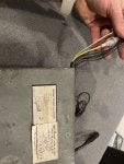
Thanks for everyone's feedback! As far as the two "grounds", one is for grounding the negative return on the internal components (white) and one is for grounding the case (black, which actually goes directly to the case.) The original Alfa also traced the white wire to ground. I think this is similar logic to the three prong plugs that could short to a conductive metal housing that might find whoever touches it as a shorter path to ground rather than a direct path through a grounding wire. In these radios, since they are only 12 volts, I believe it is more to protect the components if there is a lightning strike to the antenna or to help with noise suppression or something like that (I know, rubber tires and all but I think there is something about that). In any case, I tested the white and it is shorted to the case. The yellow is definitely main power because it has an in-line fuse, which is what keeps blowing.

I'll look more into the KP-8010 but at first glance the wire coloring is different, at least.

I did open the case and found that the PCB is badly corroded in one place and it looks like it is due to a leaky capacitor. So, hopefully, this week I'll have some time to poke at that.

Thanks again for all the feedback!

As a side note, I also got ahold of an Italian type cigarette lighter (that only fits a cigarette and you have to push the bakelite ring down to engage the lighter). Since the old standard style one was damaged I'm working on refurbishing (not that I'll ever use it) the Italian style for the fun of it and will install it.