Alfa Romeo Forums banner

De-Tensioner Re-build

59K views 141 replies 30 participants last post by  demian5  
#1 · (Edited)
Joy Joy, time to re-build the de-tensioner. :(

Getting it off is easiest to remove the circlip at the bottom of the reaction spring where it connects to the pin on the plate. Item (8). Loosen the nut on the bottom of the adjuster plate and slacken. Remove the T-belt, remove the main center retaining nut and the bottom adjuster nut and you should be able to work the d-tensioner off. Becareful not to put too much lateral force as you might bend the oil feed tube. The instructions on how to disassemble are in the Shop Manual page 01-88/82.

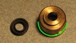
After removing the de-tensioner, it'll probably need to be de-greased. After cleanup, I noticed the actuator rod has a little cup that was installed backwards and the bellows boot is split for 90* or so at the top - No problemo as new one provided in kit.

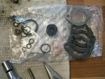
This kit has no less than 9 O-rings! Though when I look at the blow-up I can only identify 5. 1 big one on the plunger assy, 1 on the actuator rod, 1 on the feed tube, and another 2 on the back plate (feed tube again).

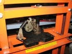
Well, no matter as I got hung-up by one of the Allen screws. Bloody thing was already 90% stripped, so maybe this has been performed before. This is a prime example of where one should only use "german torque". "Goot-n-teit"

One last thing. The pully (4) seems to have a sealed bearing. It's spinning fine, but I would like to re-pack it. If I ever get the Allen bolt off, I should be able to tell if it can be done.
 

Attachments

#2 · (Edited)
Once the pulley was removed from it's axle, I found two more O-Rings. Pulled the plate from the block and found O-rings 26A, A27 and A29 as well (see pic from Shop Manual above).

To remove the stripped allen bolt, I hacksawed a groove in it.

Then I hacksawed on an angle (to make one side wider) so I could insert a large std tip screwdriver.

Breaking the torque on it was easy at that point. Complete the disassembly, cleanup the shavings and get ready to reassemble everything. The pulley is indeed a sealed bearing. I'll check to see if it can be pressed out without damaging it. Else, it goes back in as-is. Fuzzy pic is from camera in left hand, screwdriver in right. : |
 
#4 · (Edited)
No doubt John. Now we know why a Timing Belt replacement was $1000.00. The small o-ring in the plunger assy bushing where the actuator rod goes through (20A) is a PITA to remove. Tried using a metal dental pick, micro-screwdriver & surgical clamps to no avail.

As you can see, it's way in there and over time (and heat) the rubber is now like plastic and doesn't flex at all. One has to be careful not to gouge the metal up trying to remove it or the new o-ring could get damaged and not seal properly - my guess is this is where these suckers leak. Perhaps because the seals don't get replaced 'cause trying to remove one is more painful than a friggin' root canal!

Looking at the outside of this bushing, it looks like maybe a separate piece pressed or screwed-on. Does anyone know if this is true? Would make getting that o-ring out much easier. Just don't want to "jack it all up" trying to remove it...

I'm also thinking of fabbing a splash shield in case, after all is said and done - it still leaks.
; p
 
#16 · (Edited)
No doubt John. Now we know why a Timing Belt replacement was $1000.00. The small o-ring in the plunger assy bushing where the actuator rod goes through (20A) is a PITA to remove. Tried using a metal dental pick, micro-screwdriver & surgical clamps to no avail.
View attachment 108216
As you can see, it's way in there and over time (and heat) the rubber is now like plastic and doesn't flex at all. One has to be careful not to gouge the metal up trying to remove it or the new o-ring could get damaged and not seal properly - my guess is this is where these suckers leak. Perhaps because the seals don't get replaced 'cause trying to remove one is more painful than a friggin' root canal!
View attachment 108215
Looking at the outside of this bushing, it looks like maybe a separate piece pressed or screwed-on. Does anyone know if this is true? Would make getting that o-ring out much easier. Just don't want to "jack it all up" trying to remove it...

I'm also thinking of fabbing a splash shield in case, after all is said and done - it still leaks.
; p
Image

This is where they leak nearly 99% of the time. My suggestion would be to put some good silicone in the recess let is slightly set then insert the seal with some sealer on it as well. Let it sit over night and re-install de-tensioner.
I have not had a leak and most who do this will not as well. The seal supplied is just ever so slightly too small and the silicone seals it up tight.

Nice post.
Jason
 
#6 ·
Detensioner

Toonerboy: the best drawings of all the parts of the detensioner are found in the original Busso patent for that device, which is posted on the digest at the following link:http://www.alfabb.com/bb/forums/alfetta-gtv6-1975-1986/28164-original-hydraulic-tensioner-patent.html

I have one question: what tool did you use to "pin" the detensioner to hold it back once you levered it back (presumably with a screwdriver)? I think there is a note on the AD somewhere that addresses this, but I can't find it.

Thx
Rex
 
#7 · (Edited)
F50, take a look at the first blow-up pic I posted. I think it's more accurate - even though the pic you posted comes right out of pages 01-88/82, and 01-88/84 of the Shop Manual. One cup fits in front of the bellows, and the other inside (oriented the same way) with a rubber washer inside of it. See items A9, 9A, and 10A. The bellows is 13A. In my second pic, you can see the cup on the outside of the bellows (installed backwards).

Rex, I wish I had the Alfa special pin tool A.2.0363, but for removal, I used a 3/16" (.187") drill bit. I will need to either find a brass tube (sleeve) to fit over the bit to bring the OD to 17/64". That should replicate the tool closely enough. The special tool is ~2" in length with the first 5/8" at 0.19 and back 1-3/8" is 0.27.

Hope this helps,

P.S.
No work today - 4th of July and beautiful weather. Time to eat, drink, and be thankful for the sacrifices our forefathers made for our (dwindling) freedoms.
 
#9 · (Edited)
Well, I got it out today. Application of a propane torch to soften it. Then a couple of taps with a std tip microscrewdriver to split it and I was able to grab it with the surgical clamp. It was not an 0-ring but a plastic cup!

So, a bit of a conundrum. The blow-ups don't seem to match.The first diagram shows item 18A which is a "gasket" (and looks like what came out of there, but no replacement for it in the rebuild kit). While on page 01-88/82 fig. 6V-182 the order is different (as pointed out by F50). On page 01-88/83 Reassembly, The manual says: a. Insert seal ring (1), suitably lubricated with engine oil and place it in the lower bushing of the belt stretcher housing (2). Insert piston (3) complete with seal ring (4)...

My issue is with the size of the lower bushing recess. It's too big for the little o-ring that supposed to go in there. Oil will surely get out as the piston rod goes up and down... I'll figure this out - I may re-use a part I removed earlier. Will post tomorrow.
 
#10 · (Edited)
Well, I was wrong. There is a replacement in the kit. What I thought was 10A, is actually 18A (gasket). There are discrepancies between all the blowups, and the Busso document doesn't really help. But this seal fits perfectly in the bushing. Everything else follows the diagrams well enough.

Here's a physical blowup.

I plan to install one aluminum cup inside the bellows and one outside. The kit furnishes a plastic washer 10A, to place inside (behind) the cup. I will re-use an o-ring from the old de-tensioner in place and use 10A behind the cup just in front of the bellows. Here is the backplate installed with oil feed and backplate o-rings installed.

Note the beige color of the backplate o-rings. The rest of the reassembly is covered on pages 01-88/83 thru 01-88/85
 
#12 · (Edited)
"Hassel"? Hassel isn't the word I'd choose to describe it! I spent 40minutes bent over the fender yesterday just trying to get the preload spring in there!! (Physical blowup pic, spring on left) You WILL drop that sucker a few times followed by heated expletives! I was this close to removing the A/C compressor when I got the techique down. You have to make sure that the whole spring gets in there because sometimes one or two coils are above the stop and you have to start all over again. In your right hand, hold the de-tensioner with preload spring in it's perch. Use left hand to keep spring from falling out as you slide the assembly onto the oil feed tube (called belt stretcher support pin). When you get close enough to the backplate, rotate the de-tensioner counter-clockwise and (tricky part) angle the spring so that it engages the perch and the stop at the same time. Slide the assembly home. When I finally succeeded, I just torqued the pivot and adjustment nuts down and went in for a beer and a Motrin (for my now banana shaped spine).

Anyhow, today it's time to get everything back on, so stay tuned.
 
#13 ·
Re posts #1 & 4: Item 18A (rubber cup seal) fits inside metal cup (no number in pic. 1) and o-ring 20A installs between it's flange and the detensioner body. Remove the pressed in metal cup with a vise or hydraulic press.

Re post #11: Unlike modern spring detensioners, hydraulic units are not known to cause sudden catastrophic engine failure.
 
#14 · (Edited)
That explains why I have o-ring 20A left over! :rolleyes: I didn't press out the metal cup bushing assembly. No worries, it's least likely to leak IMO.

Since I didn't get the proper pin tool A.2.0363, I improvised on F50's idea...


Follow instructions on pages 01/88-85 to 01/88-87 to install the Timing-belt. Main idea is to lock de-tensioner in full loose position and thread belt counter-clockwise going over de-tensioner last. Keep an eye on the dizzy pulley when you thread the belt over it to maintain alignment towards #1 & it's tick mark on the housing. If you're not up on jackstands, make sure vehicle is not in gear as rocking will occur and you'll move the crank & get out of alignment with your cams.

The screwdriver stop turned-out to get in the way at times. But essentially, after the belt is on, slacken the nuts securing the de-tensioner to the block, and turn engine over 2-3 time to bed it in (I used a breaker bar with 1-5/8" socket). At this time, keeping the belt tight with counter-clockwise pressure against the belt, tighten the 2 nuts. Remember to connect the reaction spring last. Remove the pin (tool A.2.0363 --> or whatever you're using in lieu of it) - So, you see, the belt is tight enough, even when the de-tensioner goes full loose.

I struggled with installing the snap ring on the reaction spring at the bottom to the pin of the plate. I decided to lose the rubber hose that covers it. Still, even with the de-tensioner locked at full loose, I was surprised to find it a PITA to get the T-belt on (very tight). Started removing right-side fan to make room for my pry bar... This was much harder than with the mechanical de-tensioner unit. Though, I second Graham's 2nd remark totally, and that's why I'm dealing with this job. Next time, I'm going the "StayBelt" (Alfa Heaven) route!


BTW - a plastic toothpick with the floss built-in makes a great tool to mark the 'P" line on the crank pulley.:D
 
#15 ·
Oil Seal Qestions

OK, I rebuilt the de-tensioner as discussed above. Using a large vice and some sockets as dowels, it was easy to press the seal holder out of the bowl and replace it.

My questions relate to the hollow bolt through which oil flows into the de-tensioner:

First, how do you get the o-rings off this thing? Do you disassemble it or is there a way to get them off without going that far? If it has to come off, what tool do you use and what procedures apply to re-installation (torque setting, permatex blue?, etc).

Second, my wife thoughtfully threw out two of the three o-rings that go on this bolt. I looked up the individual part numbers for each seal and called diFatta. They say they have them, but when they went to look they were in a big box with lots of other seals with no way to tell which seal is which.

If anyone knows how I can get these seals without buying a whole new rebuild kit, I would appreciate that information as well.

Thanks,
Rex
 
#18 · (Edited)
Well Gee Jason, iddn't that a bit like Gunga Din, showing-up with a pail of water after the regiment has already taken the hill?:D

BTW - that was one of your kits I installed. Very complete.

Anyhow, that's an interesting approach. ...who gets to clean all that out on the next rebuild?

Rex, I modified a micro screwdriver (flat tip) by bending it into a bit of a hook. That's how I got the oil feeder tube "o"-rings off. Be carful not to scrore-up the oil feeder tube doing it tho.

Oh, the de-tensioner so far is not leaking (running Castrol GTX 20w-50).
 
#19 ·
I hadn't seen that seal either until this thread popped up so I disassembled my tensioner again (was sitting on the workbench) and pressed out the piece, see pic below. Was a piece of cake to get out of there, just used a 5/8" craftsmen socket (what else are standard size ones good for? :) ) which was the perfect size and it came right out.

Before I go digging in there to get this out, the one I have in there is a reddish orange colour, I want to make sure the new one will slip in there fairly easily, it certainly doesn't look like it will! See second pic.

Also where do the two big o-rings in post #2 go?

Thanks,
Kevin
 

Attachments

#20 ·
The 2 big o-rings MAY go on the 'pivot' for the bearing. I say MAY as some have a space for them and some (bearings) do not. In post#2, you can see the step where the o-ring resides.

Make sure you put the seal in the last pic of post #19 in correctly. It works like a brake seal, so the side that is up goes towards the inside of the tensioner body. The part you pressed out should have an o-ring under it as well.
 
#21 ·
Cupped seal (gasket #18A, post #1) inserts into shaft guide (pictured above) quite easily provided shaft guide is firmly mounted in a steady vise, is slathered up with engine assembly lube and pinched together between your fingers. Carefully ease to it's final resting place with the aid of a small, blunt punch. The two o-rings in post #2 are 14MM ID x 1.5MM. They install in the reliefs on either side the early configuration of pulley #4 under mounting bolt #12. Keeps your moly grease in and the dirt out. The later pulley configuration has oil impregnated bronze bushings and no reliefs as o-rings no longer required.
 
#22 · (Edited)
OK, that may explain my issue with the two big o-rings, mine didn't have a space for those O-rings.

Thanks on saying which way the seal goes in, meant to ask that too.

Where does the O-ring that goes on the part I pressed out go? Mine didn't have one. Is it a big one that goes around the big lip that seals this piece to the bottom of the tensioner body?

Thanks,
Kevin

Edit: Added picture - o-ring goes in green area?
 

Attachments

#24 ·
Hi

Has anyone had any luck finding a new roller bearing ?

I tried the local Alfa dealer, but getting things for a GTV6 is pretty tough. They can´t even search for this model in their database, since it´s too old.

Anyway, my bearing is made by SKF, and has a 6-digit number on it. I called SKF here in Denmark, and they said the number refers to a drawing , not a part number ! They say Alfa Romeo initially ordered the bearing at SKF Italy on special order, so SKF does not have it in their program.
After that I gave up, and switched to the mechanical de-tensioner instead, but I would still like to recondition the hydraulic one. Maybe someone else can use it:)
 
#27 ·
Same bearing is used on 164 24v engine but with different center piece you have to press it out and swap the old center piece from your old bearing.

That 24v piece maybe hard to find, too as car also out of production over 10 years now. Maybe same bearing used on 156 and 166 24v models.
 
#25 ·
The SKF bearing was unique to this application; no cross-over manufacturer part. SKF 'could' produce a special run but it would be of at least 50 units or up. One callow fellow designed a roller modification employing a pair of readily available and inexpensive single row sealed bearings, sleeves and spacers but I can no longer find it.
 
#28 · (Edited)
I wonder if Rex ever got the oil supply tube's O-rings off? Hope he saved 'em so he could go and try to match 'em up. I don't see why you couldn't find suitable replacements at the local AutoZone or fully stocked hardware store...

In the world of American dealerships, there is NO WAY they would bother rebuilding this thing. The American way is to replace! (much quicker - even though they'd still book you an easy grand to do it).

When the package arrived and I saw all those O-rings, I knew it was "time to suffer". That's why I laid everything out in "blow-up" fashion to try and help my fellow DIY-ers (and myself) see where they all go.

Where does the O-ring that goes on the part I pressed out go? Mine didn't have one.
Try laying them all out kredden and see if it's still missing. Since I didn't replace that one, I'd be glad to mail it to you.