Alfa Romeo Forums banner

Radiator Fan Switch?

7.3K views 28 replies 4 participants last post by  Alfisto Steve  
#1 ·
I have a nice band new radiator, all aluminum, fits like a charm. I welded in a new coolant fan switch bung because there wasn't one on the radiator when I got it. I also welded up some brackets so it would fit nice with the stock fan on the back and line up well. I will post some pics of this. My question is:

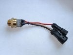
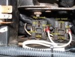
I am using an aftermarket fan switch, also with 2 temp zones, I think its from an Audi, its all they could get at napa. It has 3 male spades on the actual switch, so I plan on cutting the existing 3 wires (one black, one white, that go to a 2 conductor plug and one red that goes to single conductor plug) and put female spade connectors on the end. Can anyone tell me what the each of those wires is? Is the black a ground the white the other side of the switch for the low speed and the red for the high speed (or should I say temp zone 1 and temp zone 2) If anyone could clear this up it would be greatly appreciated. also, can I jumper 2 of these wires together temporarily so that the fan runs all the time until the switch comes in on monday? I already jumpered out the low speed resistor, I am just wondering if I can still get the fan moving in the interim since I have no fan switch.

Best,

harrison
 
#2 ·
Can anyone tell me what the each of those wires is? Is the black a ground the white the other side of the switch for the low speed and the red for the high speed (or should I say temp zone 1 and temp zone 2)
I used an aftermarket fan switch a few years back (see below). I think your "Audi" switch probably has the same labels. Yes, I think black is ground, 1 (white) goes to lower speed relay and 2 (red) goes to high speed relay. If you want to make sure or if the labels are different, you can heat up the fan switch in water over a stove (or even use a heat gun) and check the connectivity between the terminals using a multimeter.

can I jumper 2 of these wires together temporarily so that the fan runs all the time until the switch comes in on monday?
Yes, to make fan runs all the time:
- connect black and white (of the old fan switch) to run low speed
- connect black and red to run high speed
- connect all three? This will still only give you high speed :)
If you have time, I suggest wiring up a manual fan control switch in your cabin. It will come in handy!

I already jumpered out the low speed resistor
I do not suggest putting a jumper across the low speed resistor (if that's what you've done), there's already a high speed path (i.e. through the high speed relay) so I don't see the need to make another high speed path! But if you do, make sure you use a wire with same or bigger gauge wire than the brown and blue wire that go to the resistor. It has to carry high current as much as 40A - or the jumper wire will fail before the the 40A fan fuse blow.

I would suggest doing the control on the low current side of the relay by grounding pin 85 on the fan relay socket. This is where the fan switch provide a ground connection to when the set point temperature is triggered.
 

Attachments

#3 ·
I tried jumpering out the switch so that the fan would run all the time, temporarily until the new switch comes in. However, I can't get the fan to come on at all. I tried jumpering white and black and also all three, but nothing. Anything I could check to confirm? 40A fuse is good, as is the one under the dash (the lowest right hand one, correct?)

Any suggestions?

Harrison
 
#4 ·
White wire hooks to brown wire and black wire hooks to black wire in chassis 2 wiring connector and red wire hooks to single connector with brown and white wire.

black is ground wire for both low and high speed fan relays brown wire for low speed relay and brown-white wire for high speed relay.

With key on jumper brown wire and black wire in 2 wire connector that white and black wires from fan switch hook to with a paper clip and low speed relay under middle black cover should click and if resistor in radiator fan shroud good or larger medium sized brown and blue wires jumpered together for it fan should run on low.

Jumper brown-white wire that hooks to red wire to black wire in 2 wire connector with key on and high speed relay next to LS one should click and fan run on high speed.

You can test fan by itself and by pass relay circuits by grounding medium sized brown wire going to low speed resistor to chassis to see if fan, 40a fuse bar and fan wiring are OK as fan should run on high.

Report you findings/ results.
 
#6 ·
Should the brown low speed resistor wire be grounded with the others jumpered to test relay bypass? Or does it not matter if the other are jumpered.
 
#7 ·
Brown medium wire to resistor is ground wire from fan motor so grounding it makes motor run without using low or high speed relay circuits. Just ground it alone to chassis as a test that large red wire from battery and 40A fuse bar, fan motor and motor wiring are good. If motor spins freely by hand and does not run with above test and red wire has 12v past fuse bar then inspect red and brown wire connector at motor.
 
#9 ·
No, so now that fan runs doing that test do relay test with key on ground small brown and brown-white wires individually to chassis each relay should click if they don't be sure that 7.5A (10A if 94-95 model) relay fuse has power in fuse box with key on.

If low speed relay clicks with small brown wire grounded, resistor good, hooked up with medium blue and brown wires or two wires jumpered to bypass resistor then fan should run. If it does ground brown wire to black wire in same connector if it doesn't work then small black ground wire bad to chassis ground point.

Repeat process with brown-white wire for high speed relay. it uses same black wire ground point.

Again report your success/findings.

Ciao
 
#11 ·
Basic fan op testings ...

Here're some basic tests. Below is a picture of the fan relay sockets (never mind the white wires that I have added).

1. Pull both low speed and high speed fan relays.

With ignition key ON:
2. Using a voltmeter, check that you have 12-volt at the PNK-WHT. If not, the cooling fan control fuse F24 (lower right corner of fuse panel) or associated wiring is bad.

3. Check that 6BRN (power for high speed fan) and 2.5LTBLU (power for low speed fan) have 12-volt. If not, 40A fuse or wiring is bad.

With ignition key OFF:
4. Using a ohmmeter, check that the 6BLK and 2.5BLK have practically zero ohm of resistance to ground.

To turn fan on:
5. Add a jumper wire and ground the BRN (where I have added some wires) terminal to turn on low speed and ground the BRN-WHT terminal to turn on high speed. You have to plug the relays back.
 

Attachments

#12 ·
Ok I am pretty confident both relays are shot. They looked in rough shape when I took the cover off and all of the above tests checked out (got 12.5 V at all location and .3 ohm resistance to ground, thats fine correct?). I don't think I'll be able to find the relay I need today as its a sunday, any way I can get a fan wired up via switch for the interim? I was thinking of putting a high current switch between the brown ground wire going to the low speed resistor and controlling it that way until I get new relays and my thermal switch...any thoughts?
 
#13 · (Edited)
Yes that will work BUT always a but because medium sized 2.5mm brown wire to resistor will heat up because 6mm red power wire into motor and 6mm brown wire coming out are carrying up to 20 to 35 plus amps to 6mm black ground wire from high speed relay which is jumper/connected by large contacts in relay with brown and white wire grounds relay energizing coil.

Are you sure you have power from fuse box to small pink-white wires to pin 86 of both relays. Pull relays and check pin sockets 86 for power switched controlled on/off by ignition switch through BOTTOM R/H CORNER F14 7.5A (IF CORRECT FUSE INSTALLED) in main fuse box.

Radio shack sells a 12v 25A rated toggle switch. I know they sell a momentary one as I just installed in a friend's 164 starter circuit for emergency starting when key relay circuit does not work.
 
#14 ·
Yes, I am showing 12.5 V at both small sockets as well as 12.5 V on the heavy sockets (the 7.5A and the 40A parts of the relay). Would they have these relays at an autozone? I hate running heavy gauge wire into and out of the cabin, I think I am going to search my little electrical parts box outside and see if I have any, and hopefully get this resolved...
 
#15 ·
You have to install toggle switch under hood or not at all.

I doubt both relays are bad but if your a/c blower motor works pull that 50A rated relay and test both radiator fan relays in it's socket as all three relays are the same 50 Amp relays.

a/c fan relay behind false firewall under black plastic tower cover near wiper motor.
 
#17 ·
Ok, I got a relay that works at Autozone. I threw it in and the fan runs! The set up I have now is: Relay in low speed socket. Low speed wires from thermal switch jumpered together. Low speed resistor bypassed. The fan runs when the key is in the ON position. I noticed that the 40A fuse was getting a little hot though, not sure if thats a huge issue.

On a different note, I took the car around the block for a spin, maybe drove 3-4 miles or so. I was gonna wash the car down and when I drove into my driveway I figured before washing I would check the tire pressures. The right rear wheel was REALLY hot, and I felt the car pulling that way. The rear brake is dragging and when I was spraying the car down that rotor was steaming and hissing because it was so hot. This is the first time I noticed this. Could it be from the E-brake on that side not releasing? Should I take the whole thing apart? I replaced the brake pads less than 1000 miles ago.
 
#18 · (Edited)
Fuse bar maybe getting hot from running fan on high speed with resistor wiring bypassed so 6mm high speed wiring now trying to ground through smaller 2.5mm medium wiring.

Chances are unless right parking brake cable frozen in housing or parking brake lever frozen in caliper you have a bad master cylinder seizing caliper.

Whats the deal on this 164 a rescue project off road for long time?

Did you test both fan relays in blower motor relay socket?
 
#19 ·
The car sat for about 7 months or so while the engine was being rebuilt. I guess all these issues popped up while it was sitting, but I am trying to get it back together to road worthy condition! Its a good car, fresh engine, its just a couple of these nagging problems that are keeping her off the road. I want to get everything resolved, which at this point include:

Needs O2 Sensor installed (easy)
Needs Cooling Fan Fixed (easy-ish)
Needs Left Rear Brake Resolved (dont know)...
 
#23 ·
Update:

Car is in good running shape, but have yet to resolve the fan issue. Was hoping I could install this product (see link) as the new retrofit radiator has a 3/8 inch bunch for temp sensor.

However, it says that it is ground switching...Could this be accomplished by taking out both relays and basically re-wiring for the relay included in the kit?

Also, what temperature should the fan really come on at? If its single zone (so high speed only) what would people suggest?

Derale Cooling Products 16749 - Derale Performance Deluxe Adjustable Controllers with Pipe Threaded Probes - Overview - SummitRacing.com
 
#24 · (Edited)
Your making this too difficult. Just get the original setup working, it works well the way the Alfa engineers decided to do it. No need to re-engineer what they already did correctly the first time. Follows Steve's exhaustive thread on diagnosing and fixing the original setup and forget about it. Excuse the bluntness, but if you can't follow the information Steve has posted in his thread, than your not in a position to be doing any re-engineering anyway, IMHO. Most of the issues people have with the fans on these cars are caused by people undoing what Alfa did.
Charles
 
#25 ·
No no, thats not the problem! I replaced the radiator with an aftermarket one. The bung on that radiator is 3/8 NPT. What I wanted to do was put at 3/8 NPT fan switch in there and call it a day. However, I'm not quite finding the one I want (which would work with the existing set up, dual zone, etc etc).

Its not that I don't understand the set up, I'm just trying to simplify it as I already have everything else in place...If I could find a 3/8 switch that fits the bill or even a pipe fitting that switched 3/8 to whatever thread is on the original switch, those would be options as well
 
#26 · (Edited)
Sounds like radiator folks need to supply you a switch to fit radiator they sold you. I doubt they have a 2-temp dual switch for that size hole though.

If you could just get switch for that adjustable unit and if it came on a correct temp you could get single speed.

You may need to use fan cowl switch like spider uses for a/c fan. It senses heat coming throiugh radiator fins.

Maserati Biturbo sensors attach to radiator hose to turn on cooling fan.
 
#27 ·
The adjustable unit already comes with the switch that will fit the bung in my radiator. Just wondering, does the fan switch the hot or the ground in its stock configuration?

Think that might be the most painless way to go, plus they have wired for a manual switch lead so I can always throw a small switch under the dash for manual override or for A/C compressor switch on...
 
#29 · (Edited)
Here is switch you need for your aftermarket radiator 3/8 bung: Low Temp Radiator Fan Switch click on link to get pigtail connector and wire to go with switch.

Just hook small brown-white wire from high speed relay that goes to red wire on 164 thermal switch to this new switch to bring on cooling fan when radiator gets hot enough to ground new switch.

Leave low speed relay and resistor set up in place so a/c pressure will turn on low speed fan when using a/c.