Alfa Romeo Forums banner

86-88 Spider wiring diagram

24K views 50 replies 19 participants last post by  spiderserie4  
#1 ·
A color version of the 86-88 Spider diagram is currently in the works. However, the original diagrams are not clear in some areas so I'm asking for your help.

1) how many interior lights are there and their location(s)?
2) how are the lights turned on and off?
3) is there a light on the optional hardtop? if so, how does it operate?
4) what color is the small wire coming off the back of the alternator? (green?)
5) does this small wire go to the junction block on the left inner fender?

That's all the questions for now. Thanks for any input you can provide. :)
 
#2 ·
88 Grad wiring

Papa

On my 88 Grad there are 2 three position toggle type courtesy lights facing down under each side of the dash, I'm pretty sure the sequence is Left always Off/center timered door opening/Right always ON. I believe there was a map light in the glove box at one time. No hard tops except for Quads so I can't help there.
My Alt wire is red and does connect to the junction on the fender well and has at least 2 red outbound to the fuse box as well. The alt wire is in good shape and pretty heavy so it may be that it had already been replaced so I can't guarantee orginality.

Think the 87 is the same, it is covered, next time I'm under there I will check for sure....

artart
 
#3 · (Edited)
1) how many interior lights are there and their location(s)?
Not counting instrumentation or console lighting:

Two curtesy lights (one each side under dash) and operated by door in conjunction with a timer or manually by postion of the lens on the light (on all the time/on with door switch/off all the time), ignition switch light tied into curtesy light timer, hard top light (unsure if it ties in with curtesy lights), review mirror light (if equipped and unsure if tied into curtesy lights and has manual switch also), handheld map light (if equipped, manual switch on light).

2) how are the lights turned on and off?
As stated above, but I'll look in my book to see if it's got any better description on the unknowns.

3) is there a light on the optional hardtop? if so, how does it operate?
Yes, but unsure of operation or connection

4) what color is the small wire coming off the back of the alternator? (green?)
Green with black trace and ties in at the junction block on a spade/bayonet fitting toward the front of the junction block as opposed to the heavy red that ties into the conventional stud behind it.

5) does this small wire go to the junction block on the left inner fender?
Yes
 
#4 ·
Thanks, guys!! You're the best! :D

Now for dumb question #36.
Is the turnsignal flasher round or square? It's the N13 relay on the lower left on the bullet type fuse fuseboxes or the lower right on the blade type fuseboxes.
 
#5 · (Edited)
Mine is square but it's an '85 (in all honesty, I doubt the shape matters as long as the plug and electric values are the same and it clears stuff around it)

EDIT:

Book on lap now.

N13 for late S3 ('86 on) shows it being square in fusebox and drawing of device itself is square, but rectangular not cubic. (square from end, rectangular from side)
 
#7 · (Edited)
OK, digging in book deeper now:

Hardtop also has rear window defrogger tying in with what appears to be one light blue and one white wire to 'connector available' (honest, that's what the diagram calls it LOL) where the white transitions to ground and the light blue transitions to gray w/black and then carries on to 'rear service connector' then to rear window relay in fuse box (relay terminal 87. **NOTE** the other 87 terminal on the same relay goes defrogger indicator lamp via a solid pink) 85 terminal on relay goes to console cable connector (15 pin) and to the defrogger switch via an orange w/black lead from relay through connector to switch. The other relay connections are associated with fuses 3 (30 terminal on relay) and 8 (86 terminal on relay)

Rear window defrogger relay in bullet fuse box is '#3' located at the lower right corner


There seems to be a fuse box light also which is powered by a red w/no trace to fuse 2 and black which ties to ground with some type of switch along the run. (something that opens/closes the circut when fusebox or fuse cover is opened or closed is what it appears to be but is undefined)

Haven't found map light or hardtop dome light circuts yet but still digging.
 
#8 · (Edited)
The hardtop has an overhead light, positioned towards the back, close to the rear window. It comes on when a door is opened, just like the other courtesy lights. One may also turn it on manually. The positions and operation are similar to those of the mirror mounted lights in the older Spiders. The defroster is operated by an extra pair of round push type switches that are placed in the cluster that has the power window switches, at the bottom of the center console, close to the ashtray. (Sorry I can't be of more help, but I'm nowhere near to the Spiders...)

Great work, Jim - thank you!

P.S. Jim, I just checked and I have the Alfa Spider '85 - '89 Workshop Manual, which has wiring diagrams, at home in NJ. You're certainly welcome to borrow it!
 
#9 ·
With everyone's help, and borrowing some info from a 1990 schematic, the following have been identified and drawn;

courtesy lights under dash
glovebox light
vanity mirror light
map light
hardtop light

What remains is;
1) there is a light on page 40-09 of manual 3748 that is labeled F3-passenger compartment roof lamp. This lamp has two black wires on the same terminal; one to the dimmer rheostat and the other makes it's way to body ground connector G54B. The under dash courtesy lights are also labeled F3 but have already been accounted for. Could this third F3 light be on the rearview mirror? Or is the mystery F3 light one of the under dash courtesy lights?

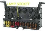
2) the fusebox light labeled F7. The diagram shows two, one in the fusebox and a second outside of the fusebox. Are there in fact two fusebox lights?
 
#10 ·
Only one fusebox light that I can find (both in book and sockets in car)

Located directly in the fusebox, and more or less centered L to R above the fuses but below the relays.


If your mystery light goes to the reostat it's a relatively safe bet it's neither a curtesy light nor mirror light as the reostat doesn't control them in any way.

It 'may' be (and this is just a reach) the light associated with the defrogger switch which would dim and brighten with the other switches and lamps in the console when using the reostat.

There seems to be a seperate lamp within the hard top curtesy light fixture that is being called a reading lamp (think overhead map light in 67 Mustang w/GT interior) and is controlled by a seperate switch, though it seems doubtful that such a lamp would fall under reostat control.

I can't find it in the diagrams I have to confirm one way or the other though.
 
#12 ·
Thanks for the fusebox light info!

The mystery light however is still a mystery. I'm suspecting it's the light in the rearview mirror. Thoughts? The two black wires on the same terminal to this light are ground wires, one from the rheostat, not power. Which leads to, what powers this light? I can't find anything relevant in the diagrams.

Except for adding electrical connector locations and this mystery light, two pages have been completed. Page one contains the lighting, power supply, starting and charging systems. Page two is accessories, senders, sensors and services. Any volunteers care to proofread these things?
 
#14 ·
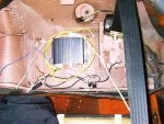
Jim, The plug above the amp and seatbeat in the picture was just laying on the rear package shelf when I bought my car. I am guessing it is for the rear window, but I do not have a hardtop. When I removed my old radio it had a 20amp inline fuse, which I thought was strange since it was going to a 7.5 amp one on the fuseblock.
 

Attachments

#15 ·
...and yet another question.

Currently drawing the fuel supply system. Could someone please verify that;

1) power to the fuel pumps comes from the main relay (not the drive relay)
2) the wire color is pink with a black stripe
3) the terminal number on the relay to which the fuelpump wire attaches

Richard,
According to the diagrams, the connector for the hardtop has six slots of which five are used. Although I don't yet know what your two wire connector is for, I think I can safely say that it's not for the hardtop.
 
#16 ·
1) dunno, as diagram I'm looking at doesn't trace that far apparently (shows to fusebox but not to any relays, unless that's another page)

2) Diagram says pink w/white stripe but car is definitely pink w/black stripe

3) see #1
 
#17 ·
Well, after a year and a half, the 86-88 diagrams are almost done. Only a few things left to finish colorizing the fuel and ignition ECUs.

I'm looking for help in identifying the wire colors on the following terminals on the fuel ECU;
1
2 - should be two wires one of which is white
4
5
9
10
12
28
29

And on the ignition ECU, the wire colors on terminals 12 & 13.

Please note that the wire colors on the above terminals on the 82-85 Spiders are NOT the same as the 86-88 (just to save some of you the time of rushing out and tearing out the ECUs).

TIA :)
 
#21 ·
The top socket is located just below the top pivot on the drivers side rear door jamb, has 5 wires to a 6 connector socket on 1987 and 1989 spiders.

The wires from the alternator go to the connection block on drivers inner fender well, in engine compartment.small green in small green out, large red in 3 large red out. The 86 green is light green and the 89 is dark green, no signs of a trace on either.

I think that the 86-88 diagram will also work for an 89, there seems to be no real difference.

Thanks for the good work on the BB all.
 
#23 ·
Fuel ECU

1 Black, mine has a short yellow to the black but I think not original.
2 White, One wire only!
4 Gray with Green trace
5 Black
9 Blue with White trace, 2 Wires
10 Red with Black trace
12 Blue with Black trace
28 Black
29 Red

Ignition ECU

12 Orange
13 Orange with Black trece
 
#25 ·
wire colors at injection ECU

Hello Jim,
Great work, the 86-88 Spider wiring Diagram. As I said, I think my 89 is identical to my 86. I have not found any major differences in the wiring. The fuse/relay/flasher panel is different swing and the knee panel is a bit different but the electrical seems identical.
The colors that I posted are from the 86. As soon as convenient I will check the 89.
Thanks for what you are doing, I hope to use the final product. Most of my electric problems are solved but I will keep notes and share solutions. I have an interest in some circuits which can be simplified or improved.
I.E. a starter relay took care of my start problem and probably saved me having to replace the ignition switch. Headlight relays are on the forums and are to happen soon to relieve the switch and improve headlight performance. Also going to remove the Great Circle fuel pump wire routing.

Thanks again, Martin
 
#26 ·
The complete redraw of the injection system is proceeding nicely (I've changed the format from a diagram to a drawing). There are of course a few more questions.
The altitude compensator; how many wires are on terminal 9, one or two?
How many wires on ECU pin #6, one or two?
Main relay - any wires on terminal 87b?
 
#27 ·
With the help of a number of contributors, the 86, 87 & 88 Spider wiring diagrams are FINALLY finished! :D Please see this post for a list of available color wiring diagrams and how to get one.

Many thanks to Darren, Martin, Mark and a number of others who took the time to answer all of my questions. Without their help these diagrams would not have been possible.