I have decided to understand the Milano speedometer system and I am starting this thread so that I can share knowledge with other interested Alfisti.
I no longer own a Milano. I sold my two Verdes a few years ago but I now have a platinum transaxle in my GTV6 and I want the speedometer to work. Mark Toro and others have posted some useful information on using a Dakota Digital box to convert the signal from the Milano "amplifier" box to make it compatible with the GTV6 speedometer. I bought a used amplifier and a sensor and they appeared not to work but I only had a test meter to work with and that turned out to be inadequate. So I took the plunge and bought an oscilloscope and here is what I have learned so far.
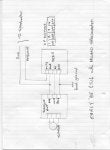
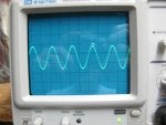
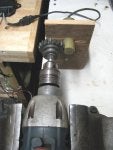
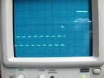
The heart of the "amplifier" is an SAF1091 chip. This chip is obsolete. You can still find them but they are expensive and that is fine with me as I am a free market guy. The spec sheet says that the inductive sensor forms part of an oscillator circuit that drops out of oscillation when a gear tooth is present at the sensor. I found it to be a little different. With the sensor connected and no tooth present the oscillator runs at about 500KHz. That is the picture on the scope which is connected to pin 7 of the chip. When a gear tooth is present at the sensor (I used the end of a chisel) the oscillator still runs but at a frequency of about 450KHz.
The output of the chip is on pin 6. With no gear tooth at the sensor pin 6 is at about zero volts. It stays at zero when the gear tooth is placed next to the sensor but it jumps to 12 volts when the gear tooth is removed and then it returns to zero. Moving the gear tooth repeatedly produces a 12 volt square wave pulse train. This is fed to the base of the transistor which provide current gain so that the pulses can drive a low impedance meter.
I am getting another "amplifier" and I will test it to verify that it works the same as the one that I have. I also bought a couple of SAF1091 chips that I will use when I get my hands on an amplifier that does not work.
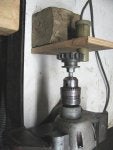
I may build a jig with a gear driven by a drill motor and a stand to hold the sensor next to it. Then I will be able to see the high speed pulse train and I will be able to check out sensors and amplifiers to verify that they work and maybe troubleshoot non-working amplifiers.
I no longer own a Milano. I sold my two Verdes a few years ago but I now have a platinum transaxle in my GTV6 and I want the speedometer to work. Mark Toro and others have posted some useful information on using a Dakota Digital box to convert the signal from the Milano "amplifier" box to make it compatible with the GTV6 speedometer. I bought a used amplifier and a sensor and they appeared not to work but I only had a test meter to work with and that turned out to be inadequate. So I took the plunge and bought an oscilloscope and here is what I have learned so far.
The heart of the "amplifier" is an SAF1091 chip. This chip is obsolete. You can still find them but they are expensive and that is fine with me as I am a free market guy. The spec sheet says that the inductive sensor forms part of an oscillator circuit that drops out of oscillation when a gear tooth is present at the sensor. I found it to be a little different. With the sensor connected and no tooth present the oscillator runs at about 500KHz. That is the picture on the scope which is connected to pin 7 of the chip. When a gear tooth is present at the sensor (I used the end of a chisel) the oscillator still runs but at a frequency of about 450KHz.
The output of the chip is on pin 6. With no gear tooth at the sensor pin 6 is at about zero volts. It stays at zero when the gear tooth is placed next to the sensor but it jumps to 12 volts when the gear tooth is removed and then it returns to zero. Moving the gear tooth repeatedly produces a 12 volt square wave pulse train. This is fed to the base of the transistor which provide current gain so that the pulses can drive a low impedance meter.
I am getting another "amplifier" and I will test it to verify that it works the same as the one that I have. I also bought a couple of SAF1091 chips that I will use when I get my hands on an amplifier that does not work.
I may build a jig with a gear driven by a drill motor and a stand to hold the sensor next to it. Then I will be able to see the high speed pulse train and I will be able to check out sensors and amplifiers to verify that they work and maybe troubleshoot non-working amplifiers.


")