Alfa Romeo Forums banner
521 - 534 of 534 Posts
Hello Richard,

have you by any chance also managed to find a way to make the same work with 15''? Like a smaller bodied ball joint?

Thanks
Alessandro

Here`s the Original post
Discussion Starter · #170 · Jun 28, 2012

Suspension work

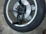
Rear suspension is finished, panhard rod and upper link finished with brakes and wheels mounted and unit centered. 16 x 8" wheels with 205-50-vr16 tires are just right.

Front suspension is ready to hang tomorrow. Spindles are effectively dropped 2.5 inches with custom built lower ball joints using chrysler screw in heavy duty BJs. No risk of failure as with using sprerical bearings(rod ends) which cannot take spring loading in shear. Modified steering arms are lowered and ackerman adjusted.


Attachments
 
Discussion starter · #522 ·
Short answer is you cannot "drop" the spindles as much using 15" wheels as you can with 16" wheels. As well you have to consider the available clearing resulting from rim backspacing.
 
Discussion starter · #523 ·
Bent Valves :rolleyes:

I had an email from a cam customer yesterday about a bent valve in a newly built head he put together.
Below is the response he got. It deserves to be on this "Technical questions" thread on the BB.

"Just be aware that when the cams have been fitted with the correct shims to set lash the cam`s bearing caps should be loosened to prevent the valve heads from hanging below the bottom of the head which would expose them to being bent. As well when installed in the head the cams cannot be turned over independently as the valves can hit the opposite one if both valves in that chamber are at a high lift position. These are the major cause of bent valves in a new engines".

"When the head is ready to be installed the crank shaft should be at TDC and the cams at the appropriate lobe centers, with the sprockets on the cam drive free to turn (but not the cam) while the chain is being installed. Once the chain has been tightened the cam can be positioned on the correct lobe center and the 5mm bolt installed in the appropriate holes in the sprocket and it`s carrier. Then the 22mm nut tightened but not the metal lock tab as corrections are commonly required."
 
Hi Richard, I have a question regarding the wire tie method. So I have C&B 10.9 cams on in and ex, with 0.16 (in) and .18 (ex) timed to 102 (in) and 104 (ex). I'd like to see if I have clearance to go to 100 on the intake and 102 on the ex. I have run a wire tie through the plug hole and then turned the engine over both ways and it seems to have a lot of clearance. I'm worried I'm doing something wrong, though or is it that easy? I have a stock 2l with no mods. Is it normal to have a fairly large amount of clearance on a stock head with no machine work?
 
Discussion starter · #526 · (Edited)
To both Saffa and Fulcrum:

The C&B cams are quite different designs from mine. The excessive duration on the earlier initial openings require higher RPMs to start making power (Torque). But If you want to try improving the lower RPM response Try the same lobe movements below.

The Lobe centers I give WebCam are an initial "safe" and appropriate point for the cams. With these 10.8mm & 10.5 mm cams and stock pistons (any of them) you should have a very strong torque producing engine. If you are happy with it, leave it there.

If you are inclined to tune to see if there is more to be had, you can retard the intake cam one hole to 99 degrees. That will open the intake sooner and close it earlier reducing Overlap which would reduce the amount of fuel going into the exhaust during overlap (more power). But check P to V clearance before cranking the motor.
On the exhaust I would leave it at 104. But to check if there`s more Torque to be had retard it to 102LC That will open the exhaust later lengthening the power stroke. Again check the P to V clearance before starting the engine.
 
To both Saffa and Fulcrum:

The C&B cams are quite different designs from mine. The excessive duration on the earlier initial openings require higher RPMs to start making power (Torque). But If you want to try improving the lower RPM response Try the same lobe movements below.

The Lobe centers I give WebCam are an initial "safe" and appropriate point for the cams. With these 10.8mm & 10.5 mm cams and stock pistons (any of them) you should have a very strong torque producing engine. If you are happy with it, leave it there.

If you are inclined to tune to see if there is more to be had, you can advance the intake cam one hole to 99 degrees. That will open the intake sooner and close it earlier reducing Overlap which would reduce the amount of fuel going into the exhaust during overlap (more power). But check P to V clearance before cranking the motor.
On the exhaust I would leave it at 104. But to check if there`s more Torque to be had retard it to 102LC That will open the exhaust later lengthening the power stroke. Again check the P to V clearance before starting the engine.
Thank you Richard! And following your wire tie method we just run a 0.5 plastic tie between the piston and valve and turn the engine over, both forwards and back, and note any interference with the tie. On a stock engine like mine, would you expect to have interference at 99/102? I seem to be very clear at the current timing and just wrry I'm doing something wrong.
 
Discussion starter · #528 ·
To be honest I would not expect it. But at the point of the intake valve opening and the piston`s downward position will be slightly reduced with LC changes. So measure it before starting the engine.
 
Discussion starter · #531 · (Edited)
I’m happy for any idea that can solve my problem(s).
Valve lash was 0.2-0.25mm all around and two valves where 0.25-0.30mm.
I thought if I throw a big(!!) pile of money at this engine I don’t have to worry about a thing.
But now look where I am, discussing tiny little details on the internet, sending pictures, making calls, driving to places, and right now it looks like a several years long court case to me.
I’m a mechanical engineer by trade, I build several engines, mostly 600cc and 2stroke but this time I just hadn’t any motivation to do it myself but that didn’t turn out too well.

Kind regards
Chris

-----------------------------------------------------------------------------------------------------------------------------------
Although you said this "mechanic" has "said" he has worked on 100 Alfa engines" no Alfa mechanic that has been inside an alfa head would have finished this head with the cutting and use of incorrect parts. Those being the long guides inserted where the Cam Lift of the good CatCams require short guides for adequate spring height for the guides and seal height to have adequate clearances.

The guides I use in every Alfa head I build are the short bronze guides designed for use in the 3.0 liter
V6 on the EXHAUST side. (Centerlinealfa part #VG245) using the Reintz green (short seal) CLs part # is
VG191. These short guides are set in the head leaving NO MORE than 10mm -12mm above the floor, including the reduced diameter area for the Green seals to be fitted. In valve lifts less than 12mm total height above the floor is safe at 12mm. These still leave a reduced exposure in the ports for less disruption of the Fuel/air mix flow. These guides have a groove around the bottom area, and should be right below the aluminum floor of the spring pocket. Then the aluminum can be compressed to provide an additional restriction to prevent guide movement.

I suspect as I have expressed that the lash is improper depending on CatCam`s lobe profile either having no raised bump to soften seat pressures or using to much lash (over the Manufacturer`s specification. Which I have not seen)

Do you have the factory lash setting for these 2 CatCams and the "lobe lift" (not valve lift which is less the
lash settings)

I`ll see if i can find the specs of your cams on CatCam`s website.

Good luck with this.
Rj
 
Discussion starter · #533 ·
Aftermarket clutch Slave Cylinder issues:
Current aftermarket clutch slave cylinders have two issues that can cause an release problem or rattle. The most problem some one is the Push Rod to the leaver is too short. That in itself can cause the shaft to rattle and along with the aftermarket version not being fitted with a spring behind it`s piston to keep pressure on the rod and throw out bearing against the clutch fingers leaves all those parts to be able to be loose and possibly rattle.
As others have posted on the BB they have followed my "Fix" of making a pushrod out of a longer 8mm or 5/16" bolt and two nuts. The hex head of it removed and that end rounded to fit in the slave cylinder`s piston. One of the nuts, the one that actually contacts the hole in the leaver is a Teflon type lock nut and the Teflon side fits into the hole in the leaver. The bolt should have a long enough threaded part that the two nuts can be initially placed in the mid area so yje rod can be first placed in the leaver`s hole and then placed through the rubber sleeve on the cylinder and on to the piston.
That done the teflon lock nut should be screwed into contact with the leaver until the slave piston is pushed back and contacting the end of it`s bore or spring fully collapsed. Then unscrew the lock nut 1 or two turns and lock it in place. That will keep the release bearing in contact with the fingers of the pressure plate as designed.

My preferance as a racer is to have the clutch fully released with only 2 inches of petal movement. But keep in mind this is using Tilton 5.5" disk with 2 thin metal driven disk with no springs to soften the clutch feel as in factory clutches.
 
Richard, thank you for this. There's another thread that mentioned an old post from you talking about an adjustable rod, I couldn't find your original post. However, I made an adjustable rod and installed it this past weekend. Works perfectly, very happy that my clutch action is up off the floormats.
 
521 - 534 of 534 Posts