Alfa Romeo Forums banner
81 - 100 of 142 Posts
Thanks, but follow-up questions

Thanks Jason,

We are getting closer to understanding each other. I think the confusion arises from the two kits, and the extra O-rings...

1. According to ToonRboy, there are three O-rings on feed stud (picture below is from ToonRboy post#10 in this thread on page1). There are two O-rings that fit into recessed cutout areas in feed stud, but I only have one black small O-ring in the rebuild kit. Why would the rebuild kit not contain both of these?

2. What is the diameter of the O-ring 20A?

Thanks,
Sal in Norcal
 

Attachments

Thanks Jason,

We are getting closer to understanding each other. I think the confusion arises from the two kits, and the extra O-rings...

1. According to ToonRboy, there are three O-rings on feed stud (picture below is from ToonRboy post#10 in this thread on page1). There are two O-rings that fit into recessed cutout areas in feed stud, but I only have one black small O-ring in the rebuild kit. Why would the rebuild kit not contain both of these?

2. What is the diameter of the O-ring 20A?

Thanks,
Sal in Norcal
This is not correct. The brown one is for the feed stud groove.
I have given you exactly where they all go. He has old kit, disregard it.
27A- Light brown skinny o-ring is for feed stud
26A- Black small one is for feed stud.


Image

You can see it shows one larger (brown skinny) one smaller (black)

29A- Brown fat o-ring is for return hole (plate)

Newer kit like yours has a boot that incorporates the (10A) bushing found in the old kit, So at the bottom of the boot you just need 1 (9a)metal ring, on the inside of the boot you have the (10A) bushing ring and (9A) metal ring.

7A-C Clip on shaft end.

18A- Piston seal fits in the insert

20A - Black O-ring fits under lip of insert-

28A- Largest black o-ring fits on plunger top

30A- Gasket fits on top of housing.

2 lock rings for helper spring for older style. Not needed for newer 164 versions late 1991, 1992-1993 usually

2- Black o-rings left over are for non-brass inserted bearings. (not need in most cases if you have newer bearing eccentric center.
I do not know diameter. Sorry. I will try if I have time but I am busy today.


I just rebuilt mine 4 months ago with new kit exactly like I show and I have 0 problems nor any leaks at all.

Please look carefully at all pictures and diagrams, you can see where it all goes and fits. Stop thinking too much, it's not that hard. ;)
 
Re-post of post #71.

Thanks Jason!

I believed ToonRboy's theory that the beige O-ring went where he placed it in the picture because there is a recessed area in the back of the de-tensioner body that can accept that beige O-ring. I thought it was a "backup" sealing O-ring in case one or both oil feed stud O-rings fail -- wrong!

I would highly recommend you explain the difference between the old and new kits, because the earlier pages of this post and ToonRboy's pictures have become the standard and accepted method for rebuilding these units. As we have just figured out, there are some mistakes and some changes due to updates in ToonRboy's method. I believe there are 3 main points-->

1. Why does the new kit have missing pieces in the two question mark areas in bottom picture below, and where did they used to go etc. Maybe even include the size of these 2 O-rings in the left question mark area.

2. Re-iterate the point about not needing to use the 2 O-rings that used to seal the top and bottom of the old version of pulley, IF you have brass inserted bearings. Maybe even include the size of these 2 O-rings.

3. What size is the O-ring that seals the "pressed out piece" against body? Is there a recess for this O-ring? Is it necessary to replace this O-ring?

Otherwise, I can assure you that future customers will spend hours swearing and getting frustrated as I did trying to figure out the proper way to rebuild this thing. You might want to consider enclosing an exploded diagram and assembly instructions with the rebuild kit like IKEA does, as my girlfriend said, or everyone will have to wade through 6 pages of this post :).

Thanks,
Sal in Norcal
 

Attachments

I believed ToonRboy's theory that the beige O-ring went where he placed it in the picture because there is a recessed area in the back of the de-tensioner body that can accept that beige O-ring. I thought it was a "backup" sealing O-ring in case one or both oil feed stud O-rings fail -- wrong!

Right, it belongs in on the closest groove to the block, smaller black one farthest from the block. You do not need a seal on the rear of the tensioner next to the plate. Feed stud diameter is 12mm. 27A- Light brown skinny o-ring is for feed stud- is 8.9mm/so is stud recess where 0-ring fits. No way that 27A brown o-rings fits there at all. The beveled area on the back of the tensioner is just so there is no SHARP edge to slice o-rings when installed.
Also you use RED/Blue loctite on feed stud threads, no chance in that leaking, no need for o-ring. None that fit it anyway.

26A- Black small one is for feed stud.-8.0mm/recess the same on stud.

Plate hole: 13.5mm for return oil passage/
29A- Brown fat o-ring is for return hole (plate)
14mm. Little larger to squeeze in there and stick.

Small hole on plate is 13.5mm

Bearing shaft-14mm, 2 o-rings are 14mm

Insert is 17mm/ 1 o-ring is 17mm
Did not measure inner as we know which one goes there.


I would highly recommend you explain the difference between the old and new kits, because the earlier pages of this post and ToonRboy's pictures have become the standard and accepted method for rebuilding these units. As we have just figured out, there are some mistakes and some changes due to updates in ToonRboy's method. I believe there are 3 main points-->
Well I will do my best. The old kit has 2 extra small o-rings, Just extras IMO. No logical place for them.
1. Why does the new kit have missing pieces in the two question mark areas in bottom picture below, and where did they used to go etc. Maybe even include the size of these 2 O-rings in the left question mark area.

Alfa made these kits, not me. My new kits now that these are N/A have exactly what you need.Like I mentioned they made them to fit 2 styles of the tensioner and also had some extras.

2. Re-iterate the point about not needing to use the 2 O-rings that used to seal the top and bottom of the old version of pulley, IF you have brass inserted bearings. Maybe even include the size of these 2 O-rings.

Mentioned above- 14mm

3. What size is the O-ring that seals the "pressed out piece" against body? Is there a recess for this O-ring? Is it necessary to replace this O-ring?

17mm

Otherwise, I can assure you that future customers will spend hours swearing and getting frustrated as I did trying to figure out the proper way to rebuild this thing. You might want to consider enclosing an exploded diagram and assembly instructions with the rebuild kit like IKEA does, as my girlfriend said, or everyone will have to wade through 6 pages of this post :).

Well it is covered in the manual. Sorry for the confusion but this is not my own part. I supply the kit according to an alfa romeo part number.

To be honest I have never had an issue with the kits. But I may do something like that if I ever have time. :)

If anyone ever has a question they can call me anytime 9am-600pm MST. I can explain it to them, or send me the tensioner and I can rebuild it free of charge if you bought the tensioner kit from me. I also have new bearings in-stock too.
Hope that explains it??

Thanks,
Sal in Norcal[/QUOTE]

Here is how the silicone is used and where:
Image


http://www.alfabb.com/bb/forums/att...41385d1154005237-original-hydraulic-tensioner-patent-tensioner_patent_busso.pdf
 
Hello good folks of the Alfetta & GTV6 forum, please pardon my intrusion. I wondered if anyone finding this thread may also be interested in my thread at http://www.alfabb.com/bb/forums/164...-168-1991-1995/168321-rebuilt-hydraulic-tensioner-small-improvement-i-hope.html (pictures there).

I added a spring (from an office stapler) to press the seal against the outside of the housing, since I didn't see what that seal would achieve if it was just left to float around inside the rubber boot.

Cheers,
-Alex
 
Discussion starter · #86 ·
boy oh boy oh boy!

I believed ToonRboy's theory...
THEORY? The only theory I have, is the bonehead theory. "for every decent thread with concise info and illustrations, there will be an additional 5 pages of fluff due to bone-headed questions previously addressed in plain English". :cool:

I'm fairly certain that if one was to peruse through this forum you could find some fairly compelling statistics to back this up. Truth be told, I placed that o-ring on there because I had an extra and I thought I'd put it on there - for good measure. Proof-in-the-pudding is that my de-tensioner is doing it's job with "0" leaks, weeps, or otherwise drop of oil anywhere.

To all the poor girlfriends out there that are forced to wade through unnecessary posts, I, uh, :eek::confused::rolleyes::eek::p
 
Thanks for this thread. I have one question. On a 164 3.0 L 24- do they have a hydo tensioner or a machanical one? I pretty sure it is mechanical but just want to confirm. We have a mysterious oil leak on our new rebuilt engine and we are trying to rule out the tensioner. This is assuming it is mechanical and the 164 does not have a oil passage that was blocked.
 
Discussion starter · #88 · (Edited)
Wish I could tell you cchan - I've only owned 12V V6's. Normally I would say, Remove the cam cover and stick your head in there - your question will be answered (I know, probably don't need to remind you, but make sure engine is off :D). Since JJ took a zillion pics of the build, I bet you can find your answer in your resto-mod thread. At least, which tensioner you have. Where the oil is coming from? You'll have to look to find out.
 
Thanks for this thread. I have one question. On a 164 3.0 L 24- do they have a hydo tensioner or a machanical one? I pretty sure it is mechanical but just want to confirm. We have a mysterious oil leak on our new rebuilt engine and we are trying to rule out the tensioner. This is assuming it is mechanical and the 164 does not have a oil passage that was blocked.
They are hydraulic but self contained. They do not use the engine oil to work.
Tensioner would not be the source of the oil leak. If the leak is by the tensioner I may say the oil pump seal.
 
Thanks for the information. Phil confirmed that it is a self contained unit as well and will not leak like my 2.5L 12V would. There is no oil passage on this engine model. We are really not sure where it is leaking since we need to clean it up and then run it again. It is not leaking alot but enough that we want to deal with it now before it ruins the engine compartment detailing.

We just towed it to the shop and covered it up for now. Therefore, dont need to worry about it breaking or leaking more. We will look at it after the Monterey Weekend since we are focused on the other Alfa for now. Once we get it on the lift we are sure will figure it out.
 
hey jason, how much are the tensioner rebuild kits? i looked on your site but couldn't find them. if they are there somewhere, please provide a link.

i rebuilt my tensioner following all the advice in this thread and it started leaking oil almost immediately so not sure where i went wrong. now it looks like the rubber bellows/boot got pinched also but the oil shouldn't even get that far anyways. my kit was an old OEM alfa kit bought off ebay. i thought i did everything properly so i'm surprised it leaked basically from the start.
 
hey toonr, please update on your rebuild and if it was leak free....or not....

i'm doing my 2nd rebuild, this time with alfissimo's kit and i want to ensure a leak free job this time.
 
hey toonr, please update on your rebuild and if it was leak free....or not....

i'm doing my 2nd rebuild, this time with alfissimo's kit and i want to ensure a leak free job this time.
I rebuilt mine 2-3 years ago with the Alfissimo kit, and it's been fine ever since
 
Discussion starter · #95 ·
i rebuilt my tensioner following all the advice in this thread and it started leaking oil almost immediately so not sure where i went wrong.
Sorry Superloaf, but i don't think you did. I do recall you started at least two or three threads on this subject back then.

That was five years ago, so I'm fairly certain mine leaks. I haven't pulled the covers off since then, but you don't have to. How long it lasted? I don't know. But I know that it's performing it's primary job.

In the longer term, I have to say that Jason's silicon packing idea is a good one. The one little grommet/seal (called gasket), simply has too much clearance in the bush. Oil is bound to weep out sooner or later.

You want Leak-free? You're going to have to plug the oil feed gallery i'm afraid and go dry (no de-tensioning help from oil pressure).
 
thanks for the updates. when i rebuilt mine, i was using a NOS off ebay and it was an OEM alfa kit but i don't think the quality of those parts was very good. after about 2-3 years and only 10,000 miles, the orange O rings on the backing plate and oil feed stud are brittle and not much good. also, the rubber boot split fairly quickly and IIRC, the whole thing leaked from the start. and i did use some sealant as recommended by jason.

that said, jason's kit seems to be nice quality with more supple O rings. of course i'm no engineer so maybe alfa used the harder orange rings for a reason....although they don't appear to have lasted even if that wasn't the source of my leakage which looks like it was past the rubber ring on the piston shaft, next to where the sealant is recommended. i'm hoping jason's ring here is better quality....or that i just get lucky and the thing seals up. (at this point, i'd rather be lucky than skilled at rebuilding these things!)

looks like bill2000 had success with his alfissimo kit so it's good to know that it is possible.
 
I had an old tube of Toyota FIPG that I used to seal the piston shaft at the bottom grommet. I periodically stick my fingers up there to see if there's any oil around the boot, but none as of yet.
 
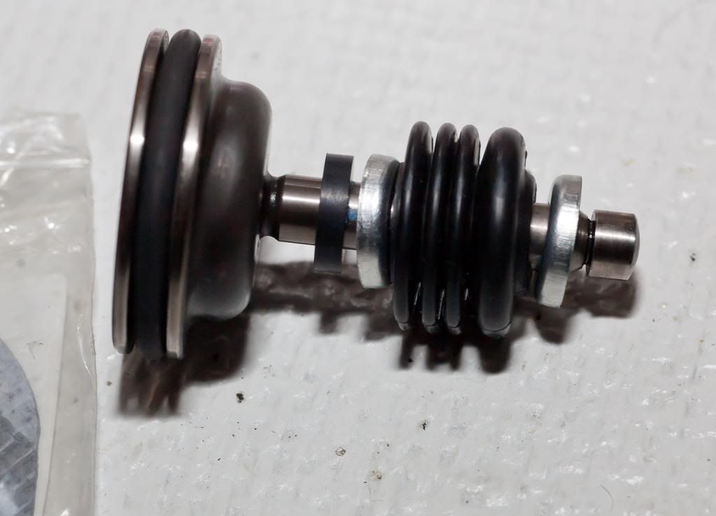
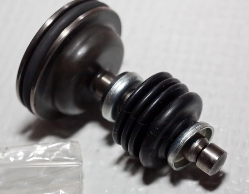
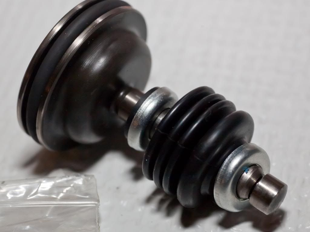
is this the correct placement of the metal & rubber bushings on the piston shaft? and i realize the bottom ones go inside the boot although not sure why there are any inside the boot at all....


and which way do the metal bushings go?

like this?


or this?

 
also, the service manual does not show any bushings inside the rubber boot. what is the proper way? i can't see what the bushings inside the boot actually do and it seems like they're more likely to pinch the boot causing damage. unless they are used as a bump stop to keep the piston from bottoming out but i still can't see how it would need this.
 
If I remember correctly (and it has been a few years so don't quote me on it!) I think I put mine back together like your 3rd picture, my justification being that the bump out at the bottom of the rubber bellows would fit nicely inside the metal bushing (or whatever you call it).

Kevin
 
81 - 100 of 142 Posts